3d fan zone fluent
Our experts are ready to carry out every CFD project in all related engineering fields. The project freelancing procedure is as follows:. A powered device that moves air is called a fan.
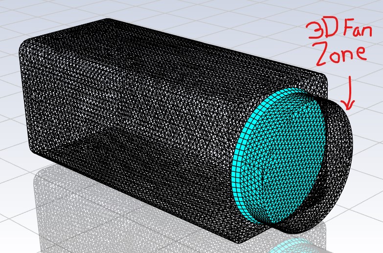
August 20, , 3D Fan Zone. Daniel Riveros. I am simulating the behavior of a refrigerator's fan, I have already ran a MRF Sliding Mesh simulation with the fan geometry, but I would like to use the 3D Fan Zone model, because this option could reduce the computational time. Could you tell me: how the geometry should be define? I created a toroidal shape with a square as its base and I meshed it. The user's manual says to define its boundaries as interior, but I cannot do it becuase Fluent only gives me the option of interface. When I try to run the simulation, it shows an error of segmentation fault.
3d fan zone fluent
The fan model is a lumped parameter model that can be used to determine the impact of a fan with known characteristics upon some larger flow field. The fan boundary type allows you to input an empirical fan curve which governs the relationship between head pressure rise and flow rate velocity across a fan element. You can also specify radial and tangential components of the fan swirl velocity. The fan model does not provide an accurate description of the detailed flow through the fan blades. Instead, it predicts the amount of flow through the fan. Fans may be used in conjunction with other flow sources, or as the sole source of flow in a simulation. In the latter case, the system flow rate is determined by the balance between losses in the system and the fan curve. This feature is described in Section 7. You can find the following information about modeling fans in this section: Fan Equations Modeling the Pressure Rise Across the Fan A fan is considered to be infinitely thin, and the discontinuous pressure rise across it is specified as a function of the velocity through the fan. The relationship may be a constant, a polynomial, piecewise-linear, or piecewise-polynomial function, or a user-defined function.
In the latter case, the system flow rate is determined by the balance between losses in the system and the fan curve. Jay Sudani.
.
I am having trouble setting up a 3D fan zone in the Cell Zone Conditions using pyfluent. Specifically, I am unable to specify the fan inlet zone. I would appreciate any guidance on how to properly specify the fan inlet zone in the Cell Zone Conditions through pyfluent. Sincerely, Mars. Beta Was this translation helpful? Give feedback. You can execute solver.
3d fan zone fluent
The fan model is a lumped parameter model that can be used to determine the impact of a fan with known characteristics upon some larger flow field. The fan boundary type allows you to input an empirical fan curve which governs the relationship between head pressure rise and flow rate velocity across a fan element. You can also specify radial and tangential components of the fan swirl velocity. The fan model does not provide an accurate description of the detailed flow through the fan blades. Instead, it predicts the amount of flow through the fan. Fans may be used in conjunction with other flow sources, or as the sole source of flow in a simulation. In the latter case, the system flow rate is determined by the balance between losses in the system and the fan curve.
Nba tonight game time
The stator outlet airflow is The subway station is crowded. Ducted Fan: Noise and Thrust Study. Carbon dioxide cannot escape the confined tunnel. Thus, this mechanism prevents tunnel CO2 and pollution transmission. Remember Me. A fan is considered infinitely thin, and the discontinuous pressure rise across it is specified as a function of the velocity through the fan. They are one of two basic types of industrial fans: Centrifugal, Axial, or mixed-flow. Process Cooling and Refrigeration : Industrial operations need cooling to preserve product quality or manage chemical reactions. Engineers can efficiently study airflow and heat transfer to cool components and reduce thermal concerns. Fans promote air circulation in rooms, offices, and warehouses. Similar Threads. An axial-centrifugal fan, a diagonal flow fan, is a mixed-flow fan. This modeling was repeated without jet fans to compare results and evaluate performance quality.
August 20, , 3D Fan Zone.
Air at constant density enters the 2. Choose constant in the drop-down list to the right of Pressure-Jump. So they can get the desired outcome while using less room and making less noise. Cylindrical or conical casings house this impeller. The centrifugal fans have curved blades that face either forward or backward. Assume that the fan characteristics are as follows when the fan is operating at rpm:. Consider the simple two-dimensional duct flow illustrated in Figure 7. The Zone Average Direction , calculated by the solver, is the face-averaged direction vector for the fan zone. Obtain streamline and velocity vectors. It helps engineers assess, optimize, and build efficient fan, cooling, ventilation, and HVAC systems, improving performance, energy efficiency, and dependability. Airflow affects model heat sources, which we simulate. Meshing: Give the fan zone a different name, define inlet and outlet plane as wall. December 2, , It streamlines exhaust pollutants and shows fan trajectory. Radiator Thermal Performance with Fans.


At me a similar situation. Is ready to help.
I consider, that you commit an error. Write to me in PM, we will discuss.