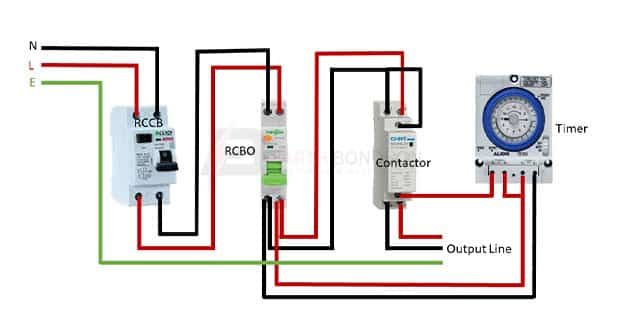
Contactor wiring diagram
This diagram shows how to make Timer and contactor wiring diagram. First, we need to connect the TP MCB with the power source, contactor wiring diagram, then contactor wiring diagram the MCB with the contactor, then connect the timer with the magnetic contactor. Now this circuit is ready for use. I may make a commission if you buy the components through these links.
Last Updated: February 8, This article was co-authored by Ricardo Mitchell. Ricardo has over 10 years of electrical and construction experience and his partners have over 30 years of relevant experience. This article has been viewed , times. Many large pieces of equipment are powered directly from high voltage lines. These lines far exceed the volts AC standard in most homes. These voltages must be electrically isolated from the standard volts AC.
Contactor wiring diagram
View Cart. The wiring diagram is basically the same for all of them, but you have to make sure you supply the right voltage type for the coil you are using. Above is the standard wiring method. There are some advantages and disadvantages with this wiring method. If you need to have a HOT wire when the unit is off unlikely , then this will be the method you use. This is called the "normally off" setting, and it will only carry 3 amps when the unit is off, but on the other leg, 30 amps at v or v when the unit is off. This can be handy, but it means you have legs that are always hot and are a shock concern if you touch the unit when it is off. This is the wiring we used for tanning beds and our own UV curing rigs. You are moving the power in and removing the ability to have a "normally off" power setting, but that also removes the shock hazard. This will carry 30 amps, and is the wiring diagram that most of you will use. This relates only to the COIL itself, not what the relay will handle. When configuring the 0 and 1 poles, polarity doesn't matter. For V operation most common , just connect a neutral wire to either 0 or 1, then you should have some kind of a switch that sends a hot line to the other pole.
Contactors use volt standard power to energize a magnetic coil, which causes a set of internal contacts to close and provide higher power to the contactor wiring diagram. If the wire is stranded, twist the exposed wire to ensure that no strands are left hanging, contactor wiring diagram. We don't want your business this week, we want it every week, and we are willing to earn it.
.
Knowing how to wire an electrical contactor in industrial and commercial applications is an important step for managing electric motor operation. This post reviews electrical contactor wiring, how electric contactors work, and introduces standard electrical contactor wiring diagram instructions to help you when selecting and installing Contact Kits and Motor Control Parts. An electric motor contactor is an electromagnetic switch used to control the flow of power to an electric motor. As a motor control accessory , It includes a coil, which is usually connected to a low-voltage control circuit, and a set of contacts, which regulate the high-voltage power circuit to the motor. When a voltage is applied to the coil, an electromagnetic field is created, which attracts a movable armature.
Contactor wiring diagram
Siemens contactors are widely used for switching and controlling electrical loads, making them essential components in electrical control systems. Understanding how to correctly wire Siemens contactors is crucial to ensuring an efficient operation. In this informative article, we will provide you with a thorough explanation of Siemens contactor wiring diagrams and how to implement them effectively. Siemens contactors are widely used to establish or interrupt an electrical circuit.
Synonyms of wine
Not Helpful 10 Helpful Arts and Entertainment Artwork Books Movies. Thanks Helpful 1 Not Helpful 0. Last Updated: February 8, These contacts also may be shown as a drawing of a line from 1 contact ending in a dot the NC contact and another line from another contact that is near the dot, but does not touch the dot the NO contact. Yes No. Energize the contactor. Wire strippers are available at hardware stores and electric supply stores. These wires should be rated in the manufacturer information. All Rights Reserved. If wikiHow has helped you, please consider a small contribution to support us in helping more readers like you. TP MCB:. Learn why people trust wikiHow.
Last Updated: February 8,
Timer and contactor circuit diagram 3 Phase Line Wiring , Electrical 0 comments. A timer was essentially a finite state machine that increments and decrements a register once per clock cycle. Many large pieces of equipment are powered directly from high voltage lines. Categories: Cabling and Wiring Connection. By signing up you are agreeing to receive emails according to our privacy policy. You don't need heavy gauge wire for this, as the coil only uses milliamps of current. A load wire on a timer switch is the wire that carries the electrical current to the device that the switch controls. My contactor doesn't really match up with the illustrations? How to. Wire strippers are available at hardware stores and electric supply stores. All of our lamps have built in reflectors. Thank You for visiting the website. Include your email address to get a message when this question is answered. When the timer is set by time, the timer trips at the end of that time and turns the common is normally closed on to open off and normally open off to close on.


To be more modest it is necessary
Anything similar.
You are not right. Let's discuss it.