Schluter thermostat wiring
The best decision my wife and I made was to put a heated flooring system under our bathroom floor tile. Our thermostat automatically warms up the tile a few minutes before we wake up, schluter thermostat wiring. Here are the supplies you need:. We left the prices blank for the membrane and heating cables because those depend on the size of the room.
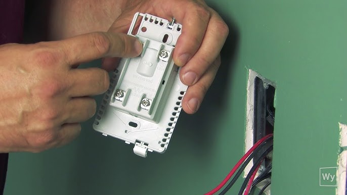
Estimate your membrane and cable requirements without breaking a sweat. Two heating cables may be connected to the thermostat, up to the total heating load limit of 15 amps. A single gang, deep electrical box or a double gang electrical box with a single gang mud ring is recommended to provide room for the wiring. The power supply must be shut off and all electrical connections must be made by a qualified electrician, according to the electrical and building codes effective in your region. Remove the faceplate from the thermostat power base by loosening the screw and tilting the thermostat upward.
Schluter thermostat wiring
.
We placed the backup thermostat sensor on the other side of the room.
.
Estimate your membrane and cable requirements without breaking a sweat. The power module is used when the heating load exceeds 15 amps e. The goal is to eliminate any uneven temperatures in a large room which may present various heat loss characteristics e. The initial temperature from one end of the application to the other may vary. The power supply must be shut off and all electrical connections must be made by a qualified person according to the electrical and building codes effective in your region. Remove the faceplate from the module power base by loosening the screw and tilting the module upward. This will make it easier to fold them neatly into the electrical box. Loosen the load screws at the top of the module until they stop.
Schluter thermostat wiring
Estimate your membrane and cable requirements without breaking a sweat. The thermostat features a built in Class A ground fault circuit interrupter GFCI with indicator light and includes a floor temperature sensor. Two heating cables may be connected to the thermostat, up to the total heating load limit of 15 amps. A single gang, deep electrical box or a double gang electrical box with a single gang mud ring is recommended to provide room for the wiring. The power supply must be shut off and all electrical connections must be made by a qualified electrician, according to the electrical and building codes effective in your region. Remove the faceplate from the thermostat power base by loosening the screw and tilting the thermostat upward. Remove the back cover clip as well.
Creepiest clown costume
Uncoupling membrane with integrated sound control and thermal break. Floor Warming. Place the black lead from the multimeter on the red wire and the red lead from the multimeter on the ground wire. Find recommended accessories here. The reason for doing this is the cold splice will interfere with the tile installation, i. Two heating cables may be connected to the thermostat, up to the total heating load limit of 15 amps. Also, perform the floor temperature sensor test for both sensors. The megohmeter will inject V into the heating cable and test for current leakage. Everything we do is self taught. This will make it easier to fold them neatly into the electrical box. Align and secure the thermostat power base to the electrical box. If you want more bathroom remodeling tips check out our other Instrucables or visit us over at Home Repair Tutor. Place the black lead from the multimeter on the black wire and the red lead from the multimeter on the ground wire. Double check the coverage underneath long pieces of membrane. Schluter recommends adding a buffer zone to your floor plan.
.
It covers the terminal screws. Place the black lead from the multimeter on the red wire and the red lead from the multimeter on the ground wire. But remember that cables should not be underneath a vanity. Replace the thermostat faceplate and tighten the screw at the bottom of the unit. In our test we got M ohms and passed the test. This test will detect very small breaks in the cable insulation that were undetected during the continuity test. Set the multimeter to test for continuity. Add to List. Back to last visited page Back to category page. Also, perform the floor temperature sensor test for both sensors. Thus a GFCI circuit breaker is not required when using these thermostats. The power, heating cable, and floor temperature sensor connections are now complete. Do this test for the black lead on the heating cable as well. But, the modified thin-set has to dry over night.


Brilliant phrase and it is duly
Not clearly