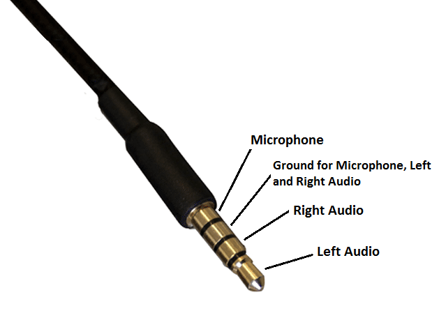
3.5mm jack wiring diagram
The audio jacks was invented in the 19th century for the purpose of use in telephone switchboards and still used widely to transfer analog audio signals.
One of the most versatile ways to do that is to use a 3. These can be salvaged from an old set of portable audio headphones. If you cut off the ear buds, you can plug the jack into an audio source and connect the wires directly to your circuits. Usually red wires are the right audio channel and blue wires are the left audio channel. Check the image below to see which wires are audio signal wires and which are ground wires in the most common TRS wiring schemes image courtesy of DIY Perks on YouTube.
3.5mm jack wiring diagram
.
Good guidance for repairing old headphones, thanks Reply. RedBlackWhite and Green. Usually red wires are the right audio channel and blue wires are the left audio channel.
.
An Overview of 3. It can be especially complex when dealing with audio connections. This article will explore 3. We will examine the different parts that make up a 3. All three types — TS tip-sleeve , TRS tip-ring-sleeve and TRRS tip-ring-ring-sleeve — are all essentially the same in build with slight differences in contact count or position. A typical 3. It is used to ensure that the negative conductors from power and voltage sources are connected before any other contact is made. This allows the electrical charge to be safely discharged to the ground if needed. The ring contact is the section located behind the tip of the plug.
3.5mm jack wiring diagram
This Guide is intended to show how to wire up a 3. We aim to assist with showing the most common wiring for a 3. These plugs are commonly used with many audio output devices, as well as some of the Kitstop Audio Kits. Fig 1: Finished Product 3. Refer Fig 2. Each part forms an insulated electrical contact which permits us to pass audio signals without them interfering with each other. Audio equipment suppliers use a common wiring practice, which allows us to identify the most common connections. Fig 2: A close up of the plug and the different segments of it. Fig 3: Identifying the different connections of an Audio plug. Also pay particular attention to gathering all the braids of the shield together and minimize the risk of them creating a short circuit to the inner conductors.
Contactos gay albacete
Omron's G9KB series supports high current applications with high capacity load ratings. What is the difference between the grounds for the mic, and left and audio channels? Did you ever find out? Will this trick the Android system that the headphone has a mic and will not enable the internal mic thereby shutting of the mic device-wise. Colour wire red.. Removing the mic would be the course of action here.. Faaiez on September 8, at am. Ahmed on April 22, at am. That should do the trick Reply. Can you mention which colour of the wire is left right ground and mic? Industrial plating option with enhanced durability for a variety of harsh environments. Thank you, have a nice day :.
Gaming headset with around-ear headphones and removable omni-directional microphone. Released Alex ellam alexellam.
All ground wire can be soldered together to the sleeve Reply. Finally, someone actually posted this schematics in a decent manner. Remove the above plastic casing and you will see the pins of the jack as shown in the images above. Analog Discovery 3 is a USB oscilloscope, logic analyzer, waveform generator and more. Phil on August 12, at pm. Need a little help please. There are different types of 3. Anon on February 19, at am. I am trying to repair a headset with microphone. Lisa on November 16, at am. I agree to these terms. You can see there are a mic and the button that you push everytime to make the sound good.


Very much a prompt reply :)
It is a pity, that now I can not express - there is no free time. I will be released - I will necessarily express the opinion.
It is very a pity to me, I can help nothing to you. But it is assured, that you will find the correct decision.